

This site uses non-intrusive cookies to enable us to provide a better user experience for our visitors. No personal information is collected or stored from these cookies. The Society's policy is fully explained here. By continuing to use this site you are agreeing to the use of cookies.
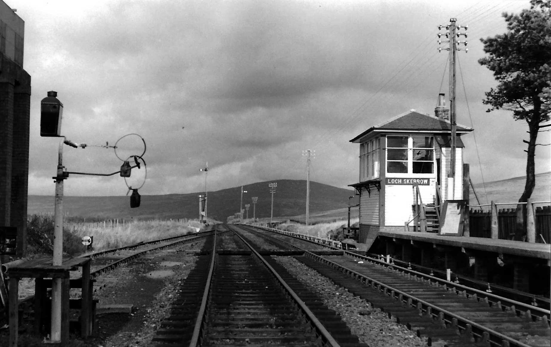
Plate 4/1 The signal box and Bryson lineside tablet exchange apparatus beside the water tower at Loch
Skerrow on the Portpatrick & Wigtonshire section on 28 September 1965. (N Forrest, courtesy Transport
Treasury)
While undertaking the hand exchange of tablets at Cummock on the Glasgow & South-Western Railway on 27 October 1908, fireman James Brown suffered an injury, as his mineral train from Skares to Auchinleck was passing at about 10 mph. This was due to the hoop into which he had placed his arm, failing to disengage properly, thereby causing him to be dragged off the footplate, from which he was lucky to sustain relatively minor injuries. Nonetheless, C Campbell, the Sub-Inspecting Officer of the Board of Trade recommended that the company investigate an improved system.
The GSWR will have been aware of the operation of James Manson's system, by virtue of his, by then, being the company's Locomotive Engineer and of its use on the Portpatrick & Wigtownshire Joint Railways, which, with the Caledonian Railway, it operated. As a consequence, the company contended that the need specially to fit the Manson apparatus to locomotives in the workshops was a costly and time-consuming process. Furthermore, in their experience a minimum speed of at least 20mph was required to affect a satisfactory exchange and not all their trains were running at such a speed at the point of exchange.
Instead the GSWR's Signal Engineer, William Bryson, developed his own design of tablet exchange apparatus in preference to that of Manson's, which more nearly mirrored the operation by hand. Bryson's apparatus was simpler and easier to fit to locomotive cab-sides or even transfer between locos, and was considered to be less susceptible to missed catches due to small transverse and height differences which could be a problem with the Manson apparatus, particularly on curved track. The downside was that in its original form it only worked at speeds up to 30mph, so trains still had to slow down to some degree, whereas, if correctly set up, Manson's operated at up to 60mph.
In the first stage of the development his method consisted of replacing the footplate-man's arm by a portable pole with a catcher at the outer end. This was in the form of a semi-circular metal piece attached at one side to the pole and the open end of which was closed by a pair of sprung arms, while on the inside of the semi-circle was a rubber pad to cushion the force of the hoop to be received. On the rear of the closed section was a sprung clip into which to insert a 14 to 15-inch diameter hoop, from which was hung a pouch containing the tablet within, to be given up. The pole was graduated along its length to assist the footplateman in knowing how far out to place the pole. This early style was put into use from June 1909, initially between Girvan No. 3 and Challoch Jct on the Stranraer Road.
Motivated by the wish to allow for a greater tolerance in alignment of the engine and lineside catcher, Bryson arranged for the tablet to be carried in a pouch attached by leather straps to a 15-inch diameter metal ring. On the ground a cross piece parallel to the track was mounted on a single timber post. At one or both ends of the cross bar an arm reached out towards the track to receive a hoop, one for each direction of travel. Above each receiving hook a delivery arm projected towards the track at the extremity of which was clamped the small tongue on the hoop to hold it in a vertical position at right angles to the track.
On the locomotive, the hoop containing the tablet to be given up was clipped to the rear of the catching pole ready to be hooked onto the receiving arm at the track-side. As the locomotive passed, the pole was held out to engage with the near side of the hoop to be collected. A degree of skill was still needed by the footplate staff, which must have been nigh on impossible during the hours of darkness.
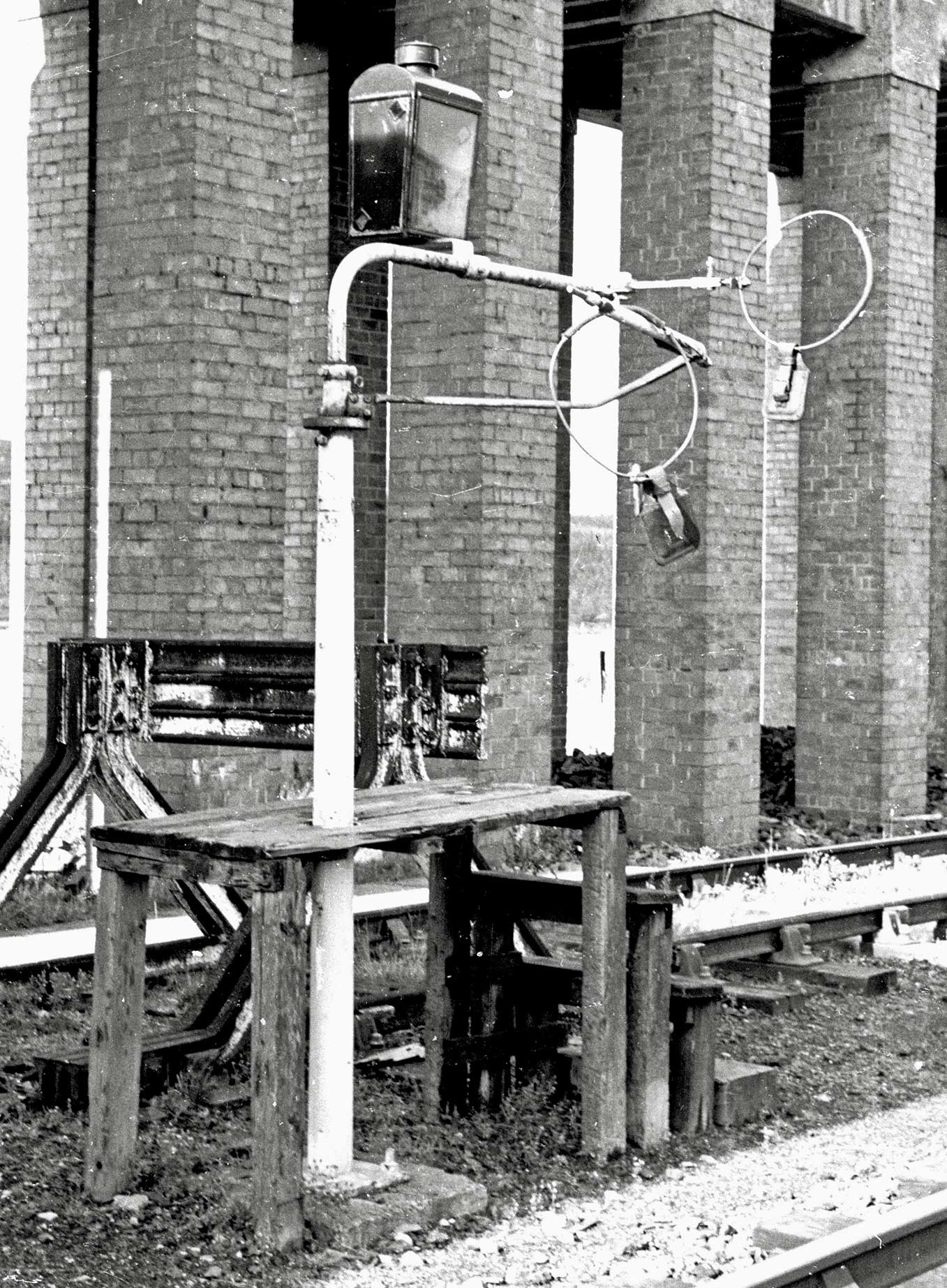
Plate 4/2 A close up of the lineside apparatus Type B at Loch Skerrow on the same occasion. This was
after the line had closed and, as above, shows an un-prototypical situation, because the both hoops carrying
the pouch containing the tablet are on at the same time, whereas in real life as one was dropped off the
other was collected by the passing locomotive. (K Fenwick)
On 22 June 1909 the Railway Department of the Board of Trade was invited to inspect and approve the system. They, however, realised that there were several such systems already in use and they had not so far approved any, instead it was their role to encourage the railways to improve safe working conditions for the staff. Nonetheless, in due course Major Pringle did visit the GSWR to examine the system and his report of 4 November that year reads as follows:
I have the honour to report for the information of the Board of Trade, that in compliance with the
instructions contained in your minute of the 30th October, I examined, on 2nd inst., the working of the
apparatus for receiving and delivering the tablet, which is in use on the single line section of the Glasgow
and South Western Railway between Girvan and Challoch Junction.
A general description of the
apparatus, together with illustrations is given in the booklet attached to the papers.
It consists of two parts. One, a post, with cross arm, fixed in the ground at a suitable place. The cross
arm is fitted with one or two hooks for catching the ring, to which the tablet to be delivered is attached,
and a socket for holding the ring which has to be picked up. The hooks swing back parallel with the line
after catching a ring, and are fitted with automatic catches which prevent them from rebounding outwards.
The other part of the apparatus is a portable "catcher" used on the engine. This is a stout pole at
the end of which is a semicircular metal attachment closed by spring jaws or fingers. The fingers yield
inwards when they strike the ring holding the tablet which has to be picked up, and immediately spring
outwards retaining the ring in the semicircle. The ring holding the tablet to be delivered is held in a
vertical position in small spring jaws at the back of the catcher, & is pulled out of the spring grip by
the hook attached to the fixed post.
The rings are about 24" in diameter, made of iron covered with
leather, and the tablet is attached to the ring by a leather strap.
The fireman rests the catcher on the rail of the tender or engine, a metal clamp on the pole indicating the
exact part of the pole which must rest on the rail.
There is little or no shock felt by the man holding the pole, and the apparatus, which practically
substitutes a pole for the man's arm, undoubtedly largely removes the risk of danger attendant upon the old
method of interchange.
Failures have occurred both in the action of the hooks to retain the rings which have been taken up by the
catcher, and in the catcher itself to pick up the new ring. These failures have involved delay, but no
injury to the men concerned.
Improvements have been effected in the automatic catchers, which prevent the hooks on the fixed post from
rebounding, whereby the probability of the first class of failure above noted above has been minimised.
A rubber pad (as shown in pencil on page 2 of the booklet) has been added to the inside back edge of the
"catcher", which adds to its effectiveness. But the general cause of the second class of failure appears to
arise from the fact that there is no vertical gauge for fixing the height at which the "catcher" must be
held, so that it may be in a horizontal position, and at the same time level with the centre of the ring to
be picked up. The height of engines and tenders vary, as well as the width. If therefore the "catcher"
pole is held out of the horizontal, either accidentally, or of set purpose when the tender is higher than
standard, the ring to be picked up, instead of striking the spring fingers at their extremities i.e. at the
centre of the semicircle, comes in contact with them near the point where they are hinged. In this case it
is only at high speeds that the blow is sufficient to open the fingers sufficiently to allow the ring to
enter within them and be (at?) retained. The apparatus is therefore (has?) liable to failure in this
respect at high speeds than at low speeds.
It would appear therefore that the most efficient use of the apparatus can only be obtained by fixing the
"catcher" pole at exactly the right elevation (so that it may be horizontal to the tender or engine. This
could be done by means of clips or otherwise. This method is referred to in the booklet, and would have the
additional advantage of obviating any possible risk to the man who holds the pole.
I think the Company might with advantage consider the advisability of fixing the "catcher" in the manner
indicated.
I have etc
J.W. Pringle, Major
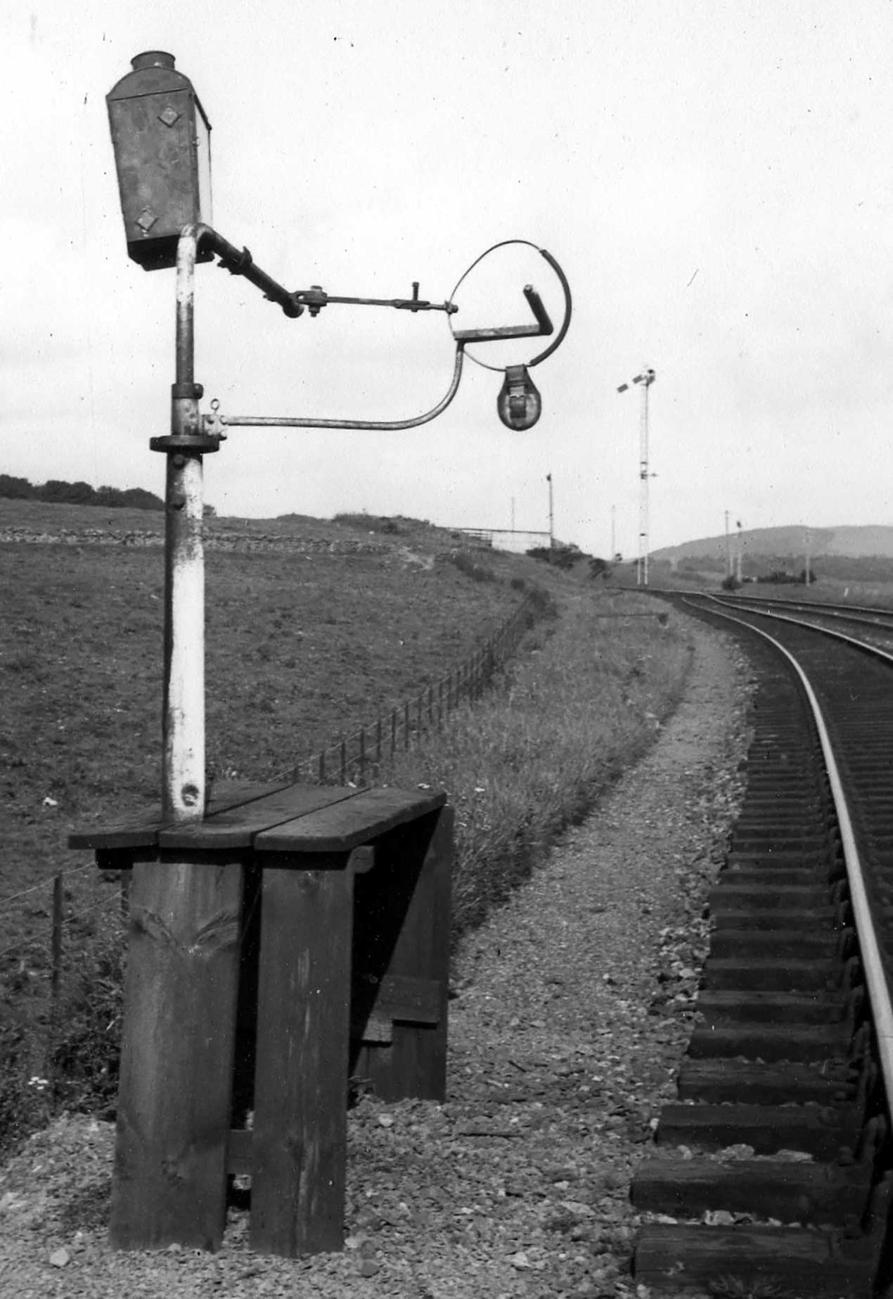
Plate 4/3 A more realistic situation is depicted at Challoch of the hoop waiting to be collected by
the locomotive from another Type B post. Note the timber platform to enable the signalman to access the
deliverer and collector arms. Also, the tall black lamp house containing two diamond shaped lights is
apparent. (Stuart Rankin collection)
Nothing seems to have been done immediately to address the shortfalls in the design of the apparatus, after which the Great War intervened and it was 1920 before an improved version was introduced. In this the lineside apparatus consisted of either one or two cast iron posts, depending on whether for uni- or bi-directional exchange, each bolted down on to a pre-cast concrete base buried in the ground. Mounted in the top of each post was a horizontal zed shaped receiving hook capable of rotating about the vertical axis and with a rubber pad in the crutch. The hook was held in position by a spring pin which engaged in ratchet teeth on the top face of the post so as to hold the hook in position once swung back. All posts, except one, were located well clear of station platforms and could be on either side of the track. So, the engines had to be fitted with sockets on both sides, while the design of the ground apparatus had to be capable of operating from either direction. Only that at Girvan was portable, the signalman inserting a squared post in a socket in the platform when required.
The catcher on the locomotive was refined so that it removed the element of skill needed by the previous hand-held pole. Instead the exchanger head was mounted on the cab-side of the locomotive, or occasionally the tender. This was slotted into a simple 4-inch diameter clip fastened to the locomotive cab or tender side-sheet at the appropriate height above rail level by a single bolt. Certain locomotive depots were provided with trackside gauges mirroring the form of the hoops to be collected, to enable the accuracy with which the exchanger head had been fitted and adjustments made if necessary before leaving shed.
The 4-inch diameter sockets could be fitted at any running shed on either side of the engine at a level just below the driver's cut-out or window. Careful examination of photographs will reveal the locomotives concerned. Those so far found cover a wide range and are listed below. When approaching the site of an anticipated exchange, one of the footplate-men would slot into the socket the engine's exchanger. This consisted of a malleable iron head in the form of a U in plan with the open end facing forward and attached to a horizontal stem by which to connect it to the engine. Its reach sideways was adjustable firstly by the use of three lengths of tubular arms and secondly fine adjustment was achieved by screwing a bolt down into one of a series of shallow holes at half-inch centres. The T-shaped head at the inner end of the sleeve fitted into the socket on the engine.
At the tips of the U shape were fingers pointing back into the U. One at a shallow angle was fixed, while the remaining gap was filled by a sprung finger. Thus, during the exchange this finger would be briefly forced open against the spring to admit the hoop and subsequently retain it. At the foot of the U was a rubber pad to cushion the force of impact as the hoop entered and was brought to a stop. On the rear of the U was another tongue piece into which a footplate-man would have clamped the hoop with the token to be given up. Once the exchange was completed, an engineman reached out and lifted the entire catcher, hoop and token and passed it into the cab before he could examine the tablet. One wonders what the combination weighed and hence how easy it was to handle as an engineman placed and retrieved the contraption before and after use.
The ground apparatus could be arranged to collect and deliver in either direction, so the socket would be fitted to both sides of the engine. For engines not so provided, the old style of wooden pole was still available with the exchanging head fitted at one end. This was rested on an adjustable brass sleeve in the engine to act as a rest and gauge.
The places at which there are ground tablet apparatus exchange posts and their position was listed the Sectional Appendices. The lengths of line and the number of section (Short/long) are given below:
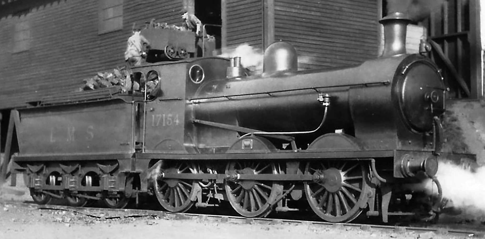
Plate 4/4 Ex-GSWR 0-6-0 Class 22 of 1890 as LMS No. 17154 and upon which the small circular socket
fitted to the right-hand cab-side can just be made out. (Author's collection)
According to the Sectional Appendices, to allow LNER trains off the ex-GNSR Strathspey branch from Craigellachie to run on into Boat of Garten without slowing unduly, the LMS provided a Bryson catcher and associated hoops, although why, when both pre-grouping companies were familiar with the Manson system, is unexplained.
The apparatus would not be used by the local trains stopping at every station, but by the boat expresses and overnight through parcel and freight trains. It is reported that in its final form exchanges could successfully carried out at speeds between 4 and up to 70mph using fibre tablets, although at the lowest speed surely a hand exchange would have been simpler. A lamp with two diamond shaped panes was positioned above the ground frame to indicate to the driver the position of the ground apparatus.
The instructions in the LMS Northern Division Appendix to Working Timetable for March 1937 ufn reads:
Hoops. Hoops for tablet exchange are supplied to signal boxes. These hoops are 15 inches in
diameter and have a tongue for holding the hoop on the delivering arm of the exchange post. For delivery
from the engine the hoop is placed in spring clip of the engine tablet catcher by means of a tongue on the
hoop.
Engine tablet catcher.- Two types of engine tablet-catchers are in use. One type is provided with a
movable guide placed on the handle, and this guide must be adjusted to suit the width of the engine. The
position of the guide can be found by placing the catcher in the delivering position. The end of the
catcher handle should then be 1 foot 3 inches from the centre of the engine. Thus, with an engine 6 feet 5
inches wide, the guide should be 1 foot 11½ inches from the end of the handle. The catcher is adjusted when
sent from the workshops to suit engine cabs from 6 feet 3 inches to 6 feet 7 inches wide. Two extreme types
of engines are marked on the handle. A portable rest for the catcher is supplied at Girvan No. 2 signal box
and at Stranraer engine sheds to suit engines with high and low cabs.
The other type of engine tablet-catcher fits into a bolted-on socket on either side of the engine cab.
Means of adjustment is provided by moving the catcher head out or in the hollow sleeve. Care must be taken
to lock the catcher securely by means of the pinching screw pro¬vided after adjustment has been made.
Catchers of this type must be adjusted at one or other of the gauge posts referred to below. Three lengths
of hollow sleeve are available to suit the various classes of engine.
Gauge A gauge of height and width is also provided at Ayr, Girvan, Stranraer, Dalmellington, and
Muirkirk engine sheds to enable drivers to adjust the catchers before leaving the sheds.
Exchanging tablets. - Should the exchange of tablets require to be made by means of the engine
catcher provided with the movable guide the fireman will place the tongue of the hoop in the spring clip of
the catcher when approaching the exchange post, and hold the catcher over the side of the engine in a
horizontal position, with the guide resting on the rail of the engine cab.
When the other type of catcher requires to be made use of, the fireman will place the tongue of the hoop in
the spring clip of the catcher prior to placing the catcher in position on the side of the engine cab. This
type of catcher must be removed as soon as the exchange of tablets has been made, and it must not be
replaced until the train is approaching the next tablet exchange post.
When placing the catcher in position care should be taken not to knock the hoop off.
NOTE.- It is important that the tablet be hung on the lower side of the hoop.
Lighting. - Lamps have been fixed on the top of the exchange posts and at night these lamps, in
addition to showing the position of the tablet hoops, will show two small clear lights to approaching
drivers thus :-
The following list shows the places at which there are Bryson's apparatus exchange posts and the positions
of the posts.
The exchange posts are to a standard gauge and suit an engine with cab rail 7 feet 3 inches to 7 feet 7
inches above rail level.
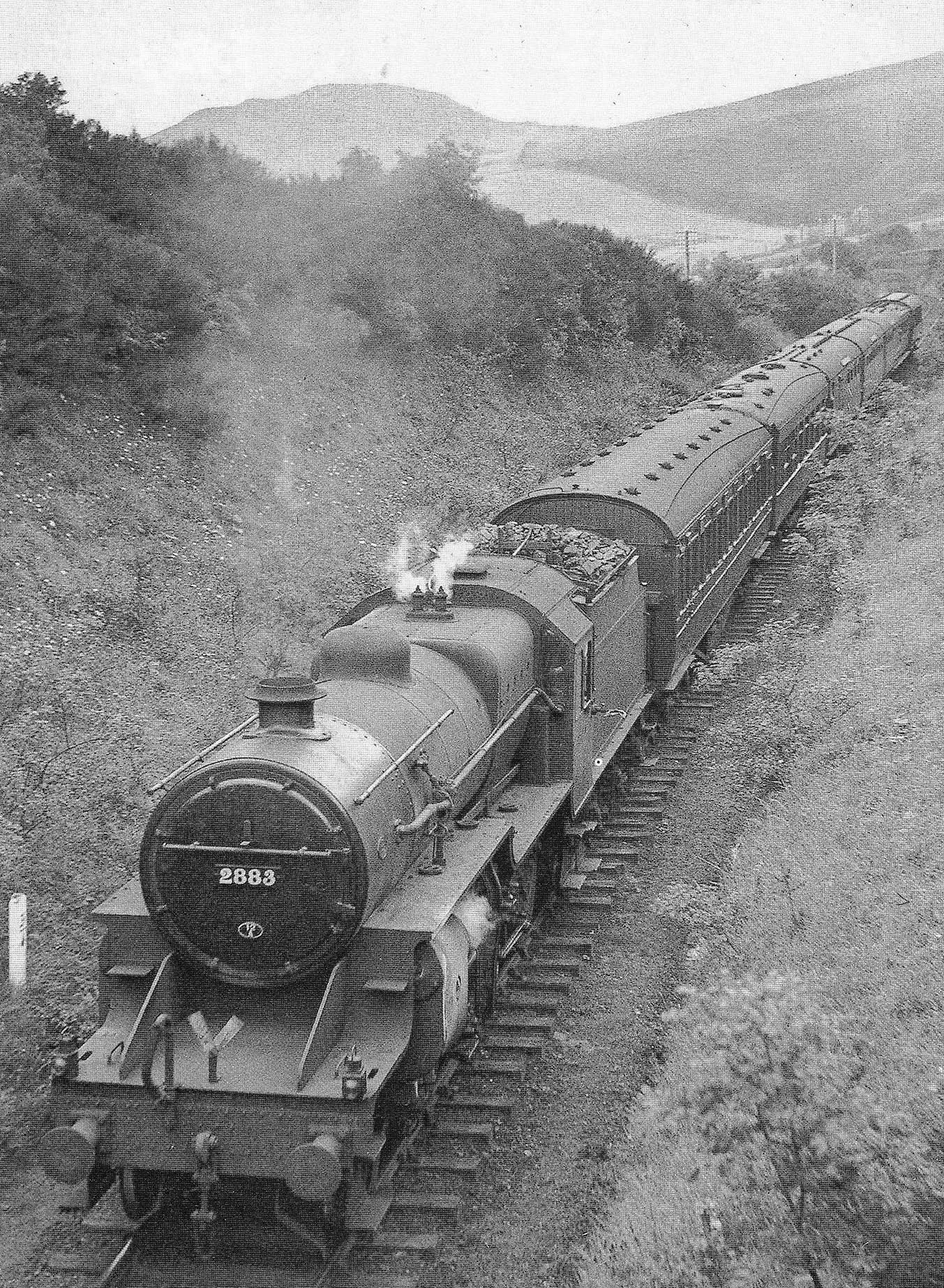
Plate 4/5 LMS 2-6-0 Crab No. 2883 heads along the single line near Pinmore, south of Girvan with the
3.50pm Fast Belfast from Glasgow (St Enoch) to Stranraer on 30 August 1939, just four days before World War
2 was declared. Careful examination under a magnifying glass, however, reveals that the Bryson catcher is
in position on the cab-side, but has yet to have attached the ring and pouch containing the tablet to be
given up, in anticipation that very shortly an exchange tablets will take place. (ER Morten)
Classes of locomotive known to have been fitted with bracket to accommodate Bryson tablet exchange fittings include:
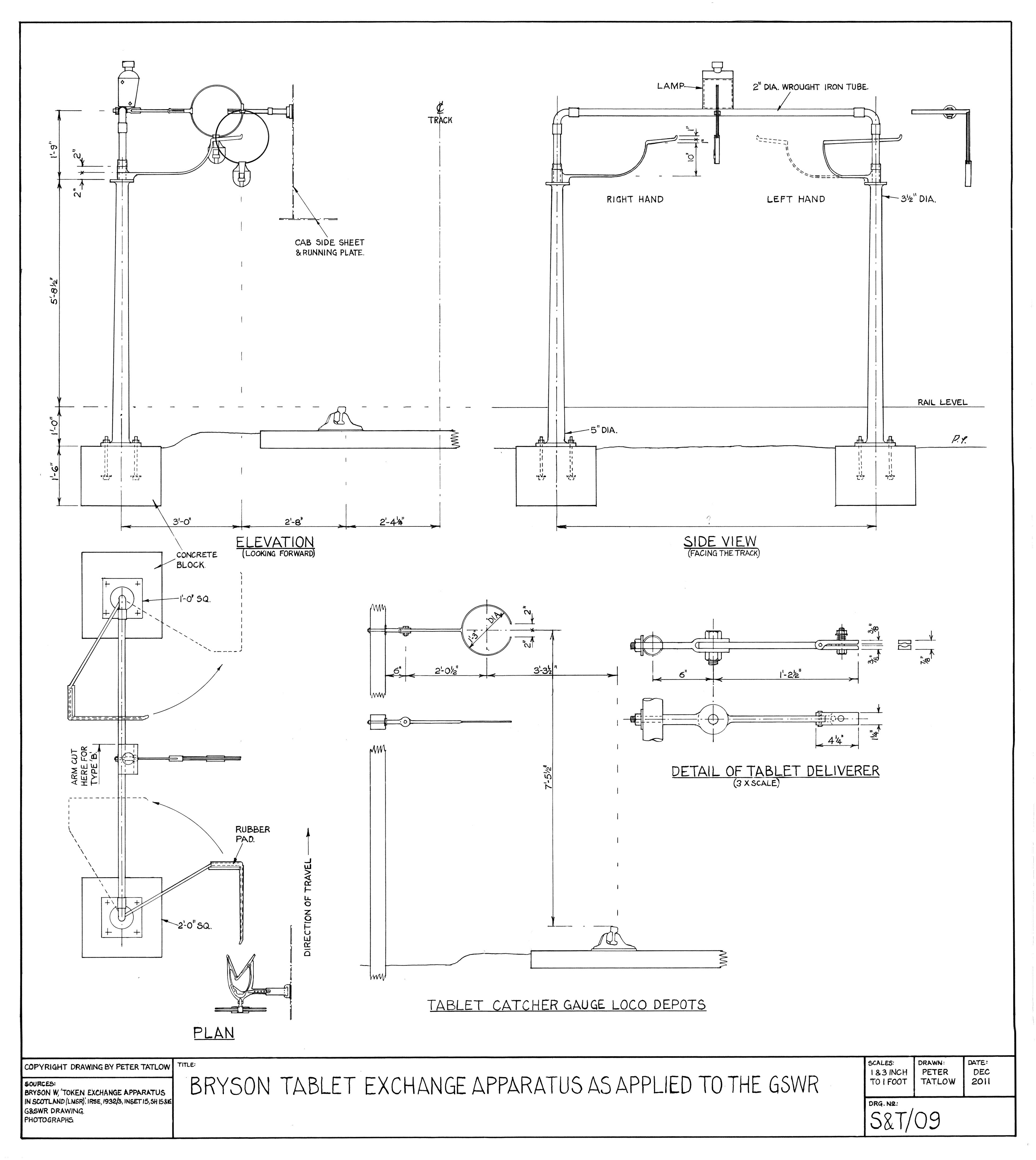
Figure 4/1 Drawing of the Bryson tablet exchange apparatus. (Author)
Whilst the Castle Douglas (No. 2) to Newton Stewart (East) section of the Portpatrick to Wigtonshire line had originally been equipped with the Manson system, it is reported that by May 1938 this had fallen out of use. A wide variety of locomotives were working between Dumfries and Stranraer, many of which were not equipped with the exchange apparatus. It was furthermore claimed that boggy ground over which the line had been constructed caused the locomotives to sway leading to missed exchanges and consequential delays. As a result, with the relatively light traffic prior to World War 2, hand exchanges had been resumed.
The overrun of Western Europe during the summer of 1940 led to a drastic change in the strategic situation leading to the rapid build up of the armed forces in Northern Ireland to repulse any threat of invasion of Ireland and to tackle the U boat menace in the North Atlantic. To sustain these forces huge quantities of armed personnel and munitions were moved to Ulster, much of it by the Stranraer to Larne ferry reached of course by means of the 'Port Road', the total tonnage passing through Stranraer increasing by 230%. In addition, early in 1941 the Government embarked on the construction of an emergency military port at Cairnryan on Loch Ryan, together with other Government and military depots, all near Stranraer. To service these double-headed 50 wagon trains plus brake van were envisaged.
With such a massive increase in traffic the LMS embarked on various improvements along the line, including doubling the line between Challoch Jct and Castle Kennedy, while eleven crossing loops were extended between Castle Douglas and Challoch Jct, together with Castle Kennedy on the Port Road during the summer of 1941. As part of the process, the number of sections was changed when Challoch Jct. closed; Dunragit to Castle Kennedy was doubled; and Glenluce to Dunragit was provided with track circuiting and direction lever. The long section box was altered from Challoch to Dunragit. The need to exchange tablets without loss of speed and by a variety of engines employed led to the resumption of automatic exchange, but this time utilising the more tolerant Bryson system at an estimated cost of £1,500 and which was available from 20 July 1942. The clips for this could be added to engines relatively simply, or the hand-held pole adopted.
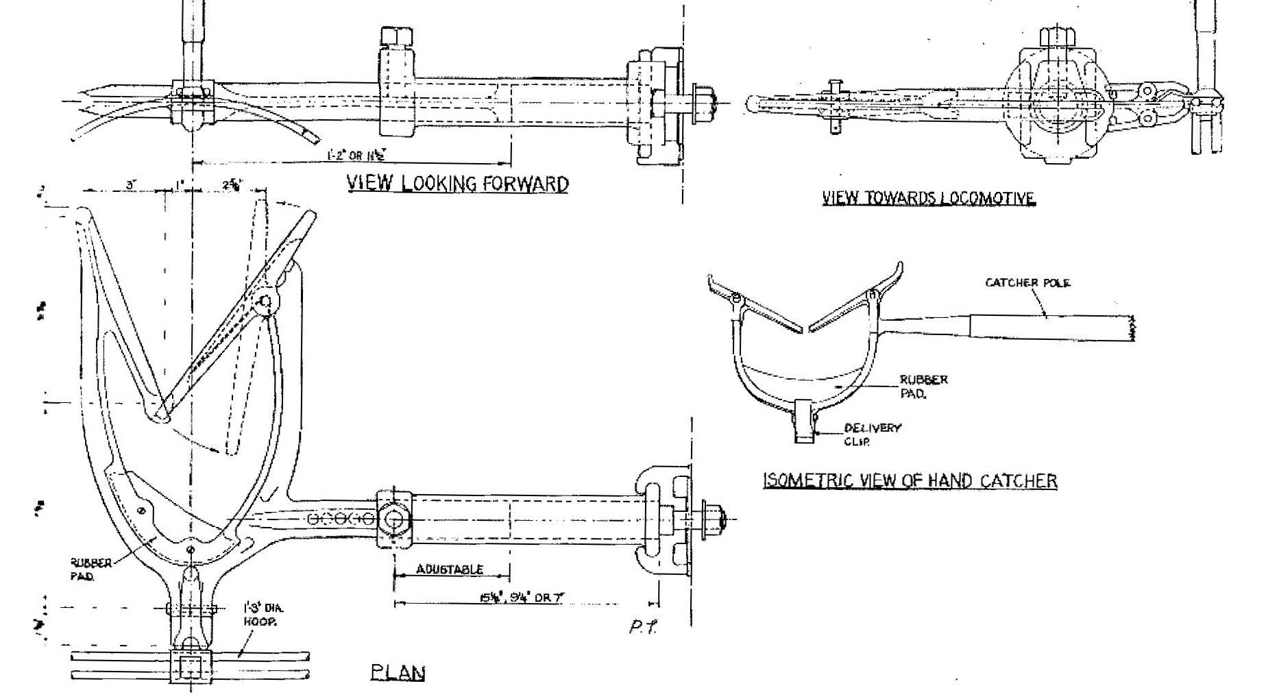
Figure 4/2 Drawing of Bryson tablet exchanger head on locomotives. (Author)
William Bryson (senior) was Signal Superintendent for the G&SWR from 1907, or earlier, at the Signal & Telegraph Works in Irvine and continued to hold that position for the G&SW Section of the LMS, eventually receiving a salary of £600 per annum. He became a member of the Institution of Railway Signal Engineers (IRSE) in 1914. After 29 years railway service, he retired on 8 March 1927 on an annuity of £350 per annum.
His son, another William, followed a similar career ending up in high technical position on the Scottish Region of British Railways until at least 1949, having passed through the posts of: Assistant to Signal Superintendent in 1929 on £400 pa; Assistant Signals (Indoor) Glasgow at £425 pa; appointed Assistant (Signals); Signal Assistant; by 1942 he was the Signal Superintendent; rising two years later to be Assistant Mechanical & Electrical and Signal Engineer on £950 pa and £1,100 two years later, all on the Northern Division of the LMS and based in Glasgow. In 1927 he too became a member of the IRSE.
Whilst father will have conceived the tablet exchange system, whether son had a hand in its development and quite who gave the paper in 1933 is unclear.
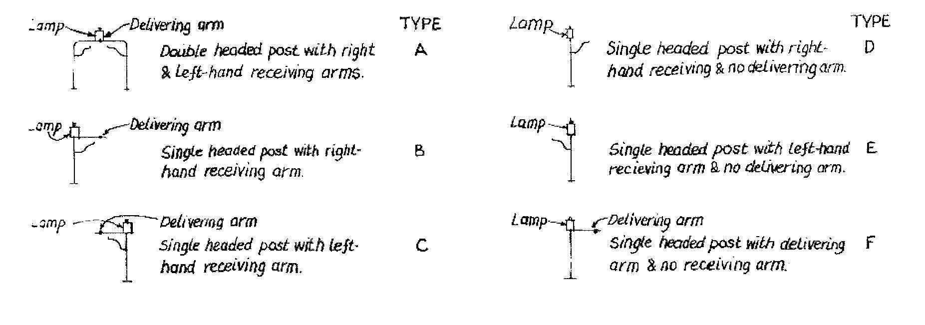
Figure 4/3 Diagrams of the types of arrangement for Bryson apparatus. (Author)
Serious modellers have no doubt been adding representations of the various forms of tablet exchange apparatus to the sides of their locomotives and catching posts at the line-side, as appropriate. For the Manson type at least, some lost wax fittings for the engine and etched brass posts have been made available by the trade, all of which adds to the authenticity
I am particularly grateful to Graham Warburton for the material he freely handed over for my consideration. Acknowledgements and thanks are also due to: the Librarians of Institute of Engineering and Technology and Institution of Railway Signal Engineers, the Ulster Folk & Transport Museum, Cultra, Michael Back, Peter Cattermole, Keith Fenwick, Mark Kennedy, Chris Osment, Stuart Rankin and David Stirling.
Site contents Copyright © LMS Society, 2026

January 30th, 2026
Site contents Copyright © LMS Society, 2026