

This site uses non-intrusive cookies to enable us to provide a better user experience for our visitors. No personal information is collected or stored from these cookies. The Society's policy is fully explained here. By continuing to use this site you are agreeing to the use of cookies.
A printed version of this article is available to members of the Historical Model Railway Society in their Journal Volume 23 Nos. 5 and 6 (July & Oct 2019). We are grateful to the HMRS for their consent to reproduce the content here.
From the early days of railways long rigid loads have been carried on two or more single-bolster wagons. For loads between say 15 and 25 feet in length, a pair of single-bolsters would suffice and in time a pair of such wagons might be permanently close-coupled and thereafter termed twin-bolster wagons. Slightly longer 4-wheeled wagons fitted with two bolsters, probably located over the axles were also introduced and known as double-bolster wagons. Longer loads could be conveyed on up to five single-bolster wagons with a number of those supporting load, whilst others acted as spacers by removing or lowering the bolster. The exact arrangement was dependant on the overall length, relative flexibility/stiffness of the load being carried and about which complex instructions were issued (1). As multi-bolster wagons became available, self-contained loads were preferred.
To reduce the number of rail joints, the adoption of ever-increasing length of rails often led to the introduction of even longer wagons to transport them. By the turn of the 19th/20th century, this had reached 45-feet and in due course 60-feet (2), for which the use of bogie vehicles usually with four or more bolsters offering points of support was the rational solution. Once available, of course, potential commercial traffic resulted in the demand for even more such vehicles. Of the constituents of the LMS, the Midland Railway seems to be first in the field with seventy-five 41-foot long 30-ton bogie rail trucks in 1899 and twenty 50-foot rail wagons in 1907 (3). Whether the Lancashire & Yorkshires sixty 40-foot long 30-ton bogie low wagons introduced in 1905 were used to convey rails or other lengthy loads may be debatable (4), but the same year the Caledonian Railway added one hundred and thirty-three 45-foot 30-ton swivel wagons, followed by another a hundred and thirty 52-feet long in 1912-1913 (5); the GSWR following suit in 1914 with thirty 45-foot 30-ton wagons; all of these being on pressed steel underframes (6). These had been preceded in 1911 by fifty 45-foot long 30-ton bogie bolster wagons for the LNWR (7 & 8). For more general use, in 1915 the MR added to stock twenty 25-ton 45-foot long bogie bolster wagons (9).
Before acquiring a further eighty-four bogie bolster wagons in 1920, however, the MR reviewed its design. Whilst the dimensions and diamond frame bogies remained the same, the capacity was increased to 30-tons (10). Instead of a 10-inch deep solebar and tie-rod trussing, the main frames were made up of four 9-inch by 3-inch rolled steel channel sections, with 3½-inch by 3½-inch by ½-inch longitudinal bracing angles to the truss-work. As before, the outer longitudinal members (solebars) were surmounted by 8-inch by 3-inch bulb angles (11). The timber headstocks, however, were replaced by a 10-inch deep channel section embracing the ends of the longitudinal members and causing the bulb angle across the ends to be ½-inch higher than the side ones. 15-inch diameter round-headed buffers with parallel housings were fitted. To accommodate varying lengths of load, the outer bolsters had alternative positions, viz: at the extreme ends, over the bogies and 3 feet further in. In addition, all bolsters were capable of being removed and to ensure their return to the wagon, its number was painted and/or incised on/in the side of each timber bolster. The floor was two and a half-inch thick by 7-inch wide wooden planks with one and a half-inch gaps every third plank to drain away rain water.
This design was then adopted by the LMS for all subsequent 45-foot bogie bolster wagons supplied to the company, but with an increase in height of the bolster from 4ft 11in to 5ft 2½in/5ft 3½in (12). The variation in height of the removable 10-inch wide bolsters was in part achieved by altering the depth of the bolsters, together with a ¼ inch increase in the distance from rail level to the underside of the solebar on the last two LMS diagrams. The diagram 11C vehicles were 4-inches wider at 8ft 8in over the body and requiring eight gussets spaced along and riveted to the solebar to support the kerb angles. This increase in width enabled the outer bolster pins to be moved out by a small amount, from 7ft 3in to 7ft 6½in and also an additional inner position was provided for them at 2ft 3¾in. Sheet cleats were fitted to vehicles to all diagrams except 11C.
3ft 1½in diameter 3-hole disc wheels were fitted on most LMS wagons, mounted in 9in by 4¼in diameter oil lubricated journal axle-boxes incorporated within diamond frame bogies (13). Whereas the MR wagons had the hand-brake applied by a hand-wheel on each side close to the headstock at one end, the LMS vehicles adopted compound lever hand-brakes on both sides inboard of the bogie at one end only (14). The U-shaped brackets projecting below the solebar on right-hand end, or off the inclined bracing of the trussing on the left-hand end are not shown on the official drawings and are presumed to have been added later to assist in the use of a brake stick. The attachment of the inclined stay to the brake lever guard on the left-hand end, to the trussing, was changed to the brake lever shaft support plate, similar to the other side, on later deliveries. This may have been to make it easier to insert the brake stick in the above-mentioned U-shaped bracket, or to avoid catching one's knuckles on the bolt head when applying the brake lever.
All such wagons were coded BBS by the LMS and BOBOL C by BR. During the grouping period, not only were these bogie bolster wagons regarded as Non-Common User and annotated by the letter 'N' at each end of the kerb rails, but were originally subject to the limitations of Specially Constructed Vehicles (SCV). In practice, however, they and the 52-foot version about to be considered, became so numerous that with time matters were somewhat relaxed. During World War 2, under the auspices of the Inter-Company Freight Rolling Stock Control, from 1 October 1941 this class of vehicle was shared between all four companies, being classified as bogie bolsters C (45ft) and D (52ft) respectively (15).
| MR/LMS 45-Foot 30-Ton Bogie Bolster Wagons –Construction Details | ||||||||
|---|---|---|---|---|---|---|---|---|
| Coy | Diagram | Page in SCV book | Drg. Nos. | Under-frame trussing | Brake | Tare weight (T‑c) | Ht of bolster | Lot Nos. |
| MR | D827 | 6 | 4226 | Tie rod | wheel | 15-0 | 4'-11" | 894 |
| MR | D827 | 11 | 5121 | Angle | wheel | 15-0 | 4'-11" | 946 |
| LMS | D1682 | 11 | 6468 | Angle | lever | 14-11 | 5'-2½" | 287, 348, 349, 392, 759 |
| LMS | 11A | 13/2228 & 6455 | Angle | lever | 15-5 | 5'-3½" | 937, 983 | |
| LMS | 11C | 13/3022 & 2232 | Angle | lever | 15-9 | 5'-3½" | 1210 | |
| MR/LMS 45-Foot 30-Ton Bogie Bolster Wagons – Building Details & Numbers | ||||
|---|---|---|---|---|
| Lot | No. built | Year built | Built by | Nos. (Sample) |
| 946 | 84 | 1920 | 154, 413, 734, 924, 1336, 1768, 208, 6866, 7179, 7212/5, 8638, 9344, 11107/11, 12183/208/50/312, 17948, 18180/93, 22374/556/718/858, 26980, 27033/112/34/84/96/301/37/42 /450/974, 30349/741, 34111/56/219/452 /569/640/81/97/965, 35287/72/629, 58287, 65481, 92567, 83148/874, 96207 /341, 97220, 117506/10-3/6/8-20/2-5/31/43, 124048, 145150. | |
| 287 | 89 | 1926/7 | Wolverton | 2384, 60238, 10684, 83635, 111827, 126360 |
| 348 | 50 | 1927 | Metro C&W | 201136, 202026, 203832, 223657, 238436, 274001 |
| 349 | 50 | 1927 | Glouc C&W | 310460, 321659, 332266, 346170 |
| 392 | 88 | 1928/9 | Wolverton | 300558, 304851, 314064, 314408, 319659, 322751, 327228 |
| 759 | 50 | 1934 | Wolverton | 290017, 290092, 290221, 290722 |
| 937 | 50 | 1936 | Hurst Nelson | 720500-49 |
| 983 | 25 | 1936 | Hurst Nelson | 720550-74 |
| 1210 | 30 | 1939 | Wolverton | 720575-604 |
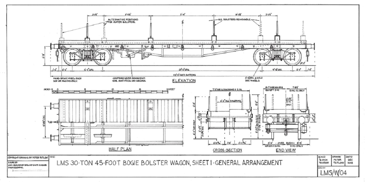
Figure 1.1 General arrangement drawing of MR and LMS 45-foot long 30-ton bogie bolster wagons to diagrams 11, 11A and 11C.(Author)
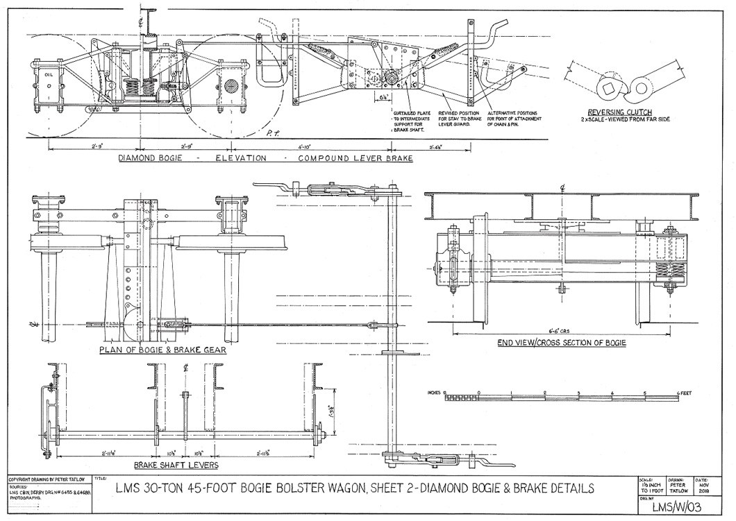
Figure 1.2 Detailed drawing of bogie and brake gear to LMS 30-ton bogie bolster wagons. (Author)
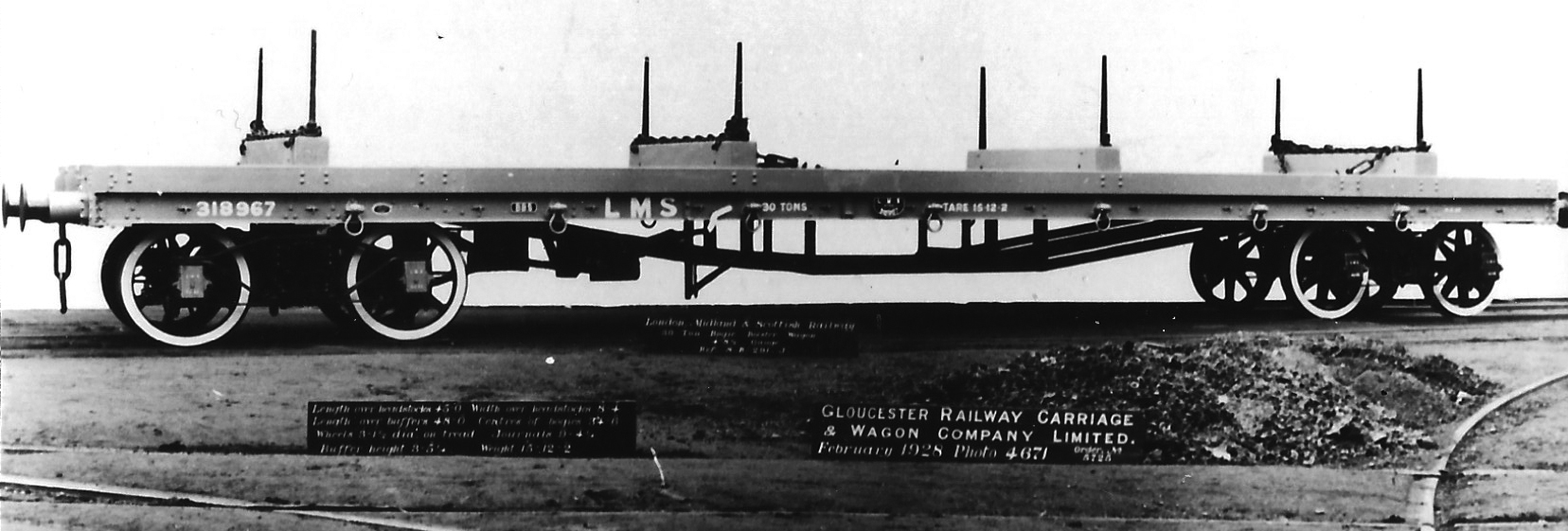
Plate 1/1 The Gloucester Railway Carriage & Wagon Co Ltd were among the earlier suppliers of
30-ton bogie bolster wagons to the LMS. No. 318967 was out-shopped in February 1928 with spoked
wheels. Note the neatly placed binding chains on three out of the four bolsters. (Author's
collection)
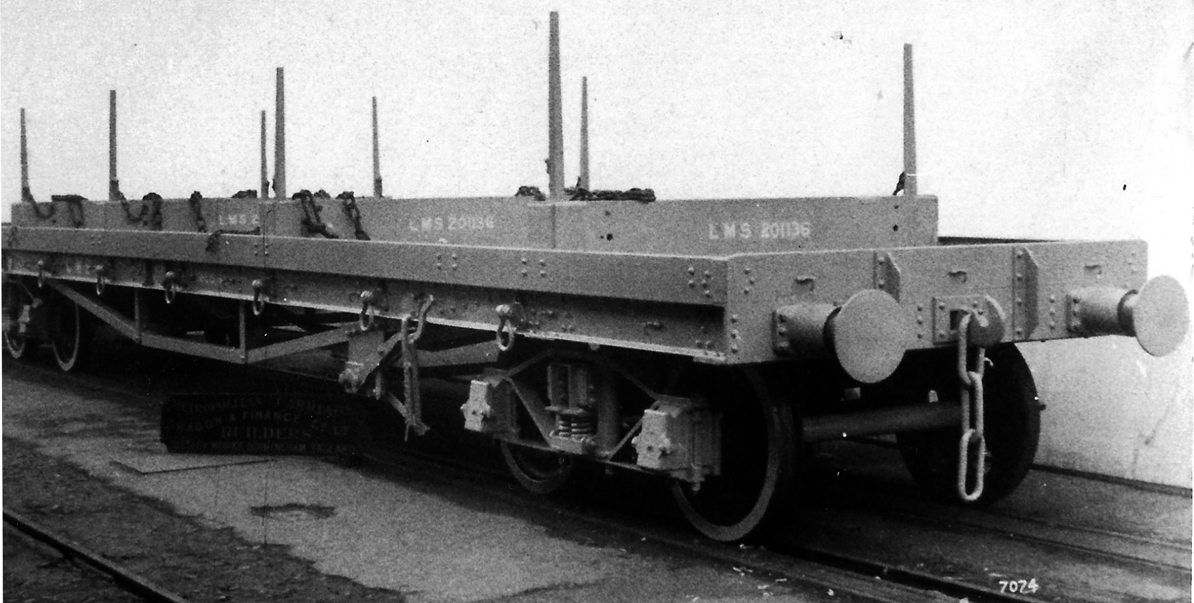
Plate 1/2 LMS 45-foot long 30-ton bogie bolster No. 201136 to diagram D11 in works grey, one of
fifty built by Metropolitan Carriage & Wagon in 1927. (HMRS, ref: ABV327)
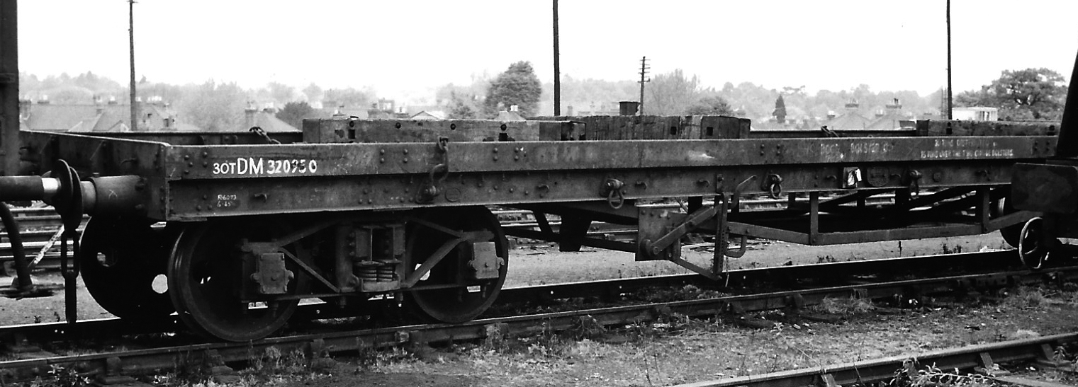
Plate 1/3 No. DM320950 later in life in Woking Upside yard in May 1968 with its bolsters scattered
on the floor. By now classified as a Bogie Bolster C, the inscription reads: 30 TONS DISTRIBUTED /
15 TON OVER TWO CENTRE BOLSTERS. (Author, ref: 35/86-15)

Plate 1/4 No. M720588 is an example of the final version of LMS 30-ton bogie bolster of increased
width to diagram 11C, built at Wolverton in 1939. It is seen here at Millerhill on 26 July 1964
recently repainted in BR grey livery. Note the brackets on the solebar supporting the bulb angle
sides, the 'U' shape hanging down from the solebar behind the brake lever and the right-hand bolster
located in the inner most position. (DP Rowland, ref: 2860)
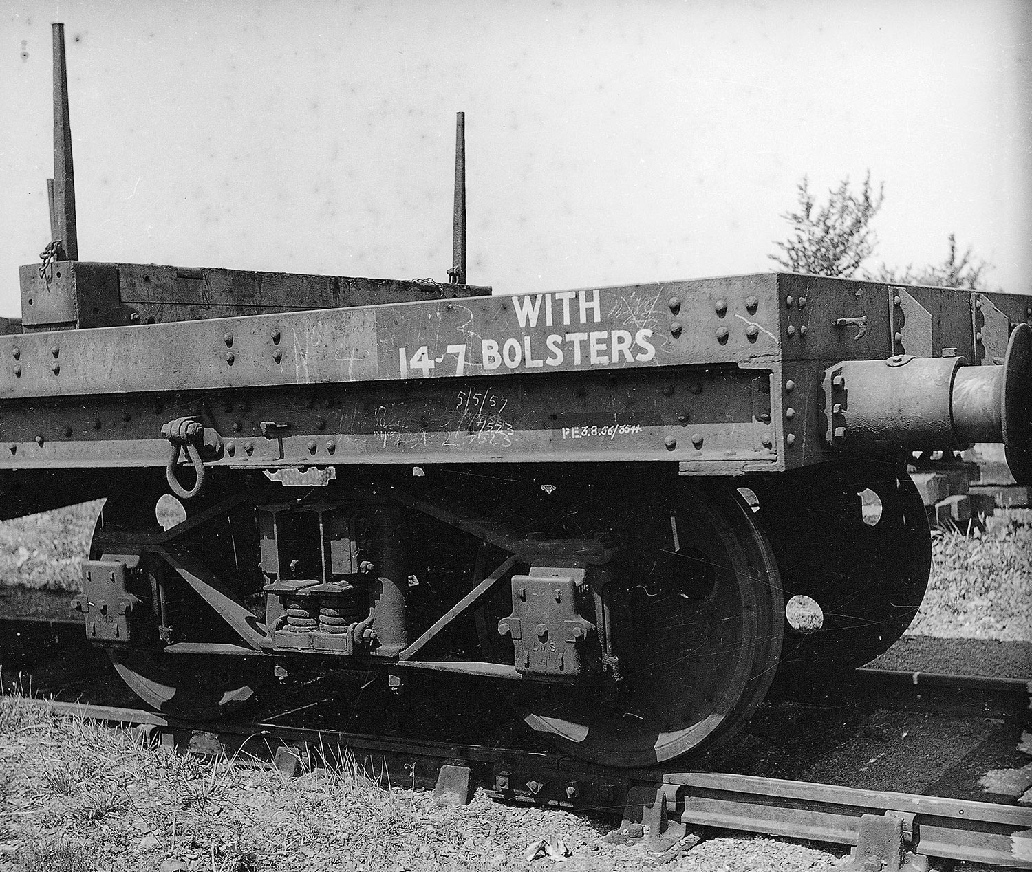
Plate 1/5 A close up of the end of No. M720522 to diagram 11A at Axminster on 15 June 1957 showing
the diamond frame bogie. (AE West, courtesy MS King, ref: R2549)
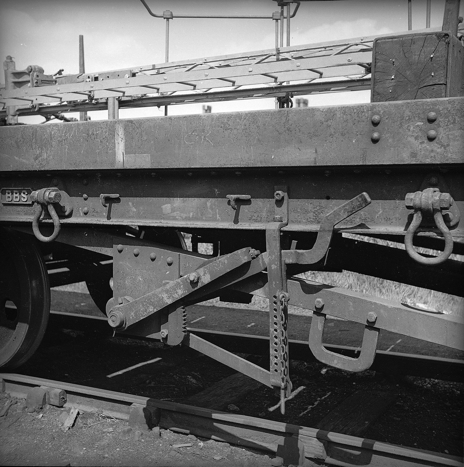
Plate 1/6 No. 314064 at Cardington on 27 June 1939 showing the 'U' section attached to the inclined
bracing angle and the tie from the lever guard tied back the brake shaft support plate. (AE West,
courtesy MS King, ref: 627)
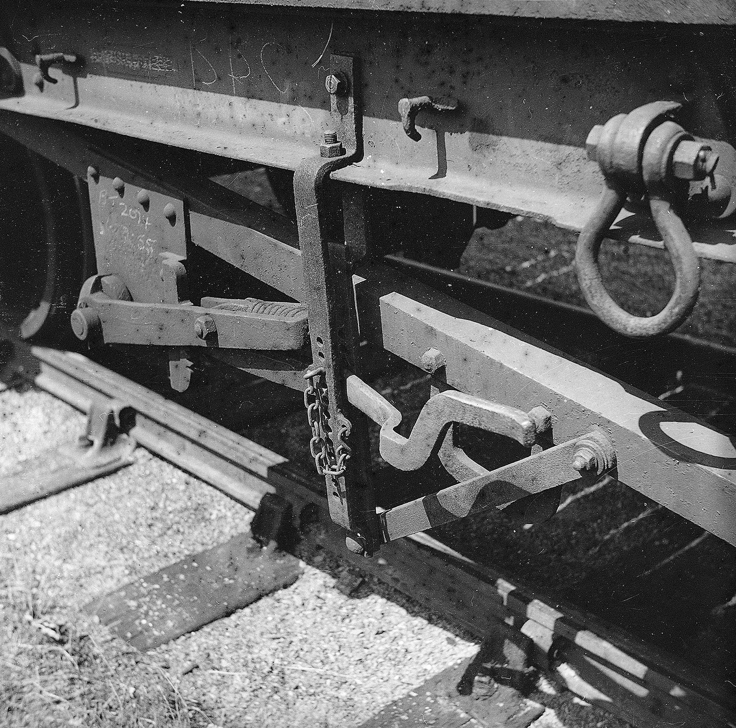
Plate 1/7 In contrast, the guard stay on No. 720522 was taken back to the inclined angle of the
trussing. (AE West, courtesy MS King, ref: R2550)
Whereas the LNER had, from 1927, only built new 40-ton 52-foot long bolster wagons with five bolsters known as Quint Ds (16), it was another eight years before the LMS introduced the first batch 52-foot in length of 40-tons capacity to Lot 841 (17) and ceased to acquire any further 30- to 45-foot bolster wagons from 1939 (18). The subsequent Lot 1211 in 1940, however, were to a reduced capacity of 35-tons (19), but thereafter in 1948 and 1949 Lots 1513 and 2021 reverted to 42-tons, the enhanced load permitted under wartime conditions (20), together with an order only fulfilled under the BR regime as diagram 470. Under LMS auspices, the 35-ton wagons were coded BBA and 40-ton BBZ, all becoming classified as Bogie Bolster D, or D Bolster under BR (21). Sheet cleats appear not to have been fitted to any of these wagons.
The frame was made up of four longitudinal 10-inch deep channel sections and headstocks with bulb angle kerb rails, probably 8-inch by 3-inch, together with angle section queen trussing. The bolsters were 10-inch wide by 1ft 3¼in high, or 1ft 2¼in high and, although removable, do not appear to have had alternative positions. The floor was made up of two and a half-inch thick wooden planks. Due to the increased length, to avoid buffer locking on tight curves, 24-inch by 14-inch oval buffers were used. Whereas the 35-ton wagons to diagram 15B had bolster pins at 7ft 9in, 4ft and 2ft 6in centres, the 40-ton wagons to diagram 18A omitted the 2ft 6in, whilst the 42-ton to diagram 18C omitted the 4ft instead. Four sets of binding chains and screw couplings were provided.
The diamond frame bogies with 6-foot wheel base carried 2ft 8½in or 2ft 9in diameter 3-hole disc wheels mounted in 10in by 5in diameter oil lubricated journal axle-boxes (22). Like the 30-ton wagons, compound lever hand brake on both sides inboard of the bogie at one end only were adopted, together, in due course, with a U-shaped bracket projecting below the solebar to the right of the lever guard to assist in the use of a brake stick.
| LMS 52-Foot 35/40-Ton Bogie Bolster Wagons | |||||||||||
|---|---|---|---|---|---|---|---|---|---|---|---|
| Load(Tons) | Page in SCV book | Drg. Nos. | Tare (T‑c) | Lot Nos | Built at | No. built | Year built | Ht. of bolster (ft‑in) | Nos. | Codes | |
| LMS | BR | ||||||||||
| 35 | 15B | 12/281 & 13/2077 | 18-13 | 1211 | Wolverton | 20 | 1940 | 5-3½ | 720710-29 | BBA | - |
| 40 | 18A | 12/281 & 13/2077 | 18-5 | 841 | Wolverton | 20 | 1935 | 5-2½ | 720000-19 | BBZ | - |
| 42 | 18C | 12/281G & 13/2077A | 18-12 | 1513 | Derby | 66 | 1948 | 5-3½ | 720020-85 | - | - |
| 42 | BR 1/470 | 18-13 | 2021 | Derby | 150 | 1949 | 5-3½ | B94100-149 | - | BoBol D | |
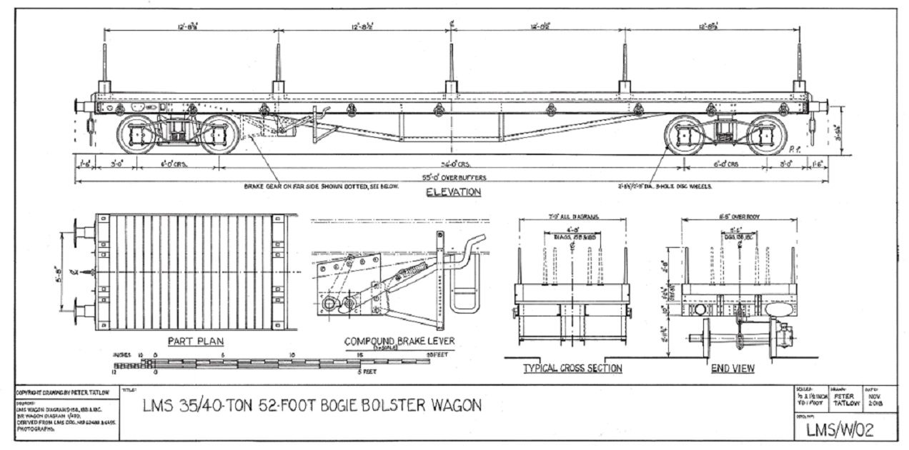
Figure 2.1 Drawing of LMS 35/40-ton 52-foot bogie bolster wagon. (Author)

Plate 2/1 An LMS 35-ton 52-foot bogie bolster wagon No. M720720 built in 1940 to diagram 15B seen at
Eastleigh on 22 May 1968 loaded with 12 by 5-inch by 25lb rolled steel universal beams. The inability
to be able to adjust the position of the outer bolsters means that the whole load was carried by the
inner three bolsters. (Author, ref: 35/86-22)
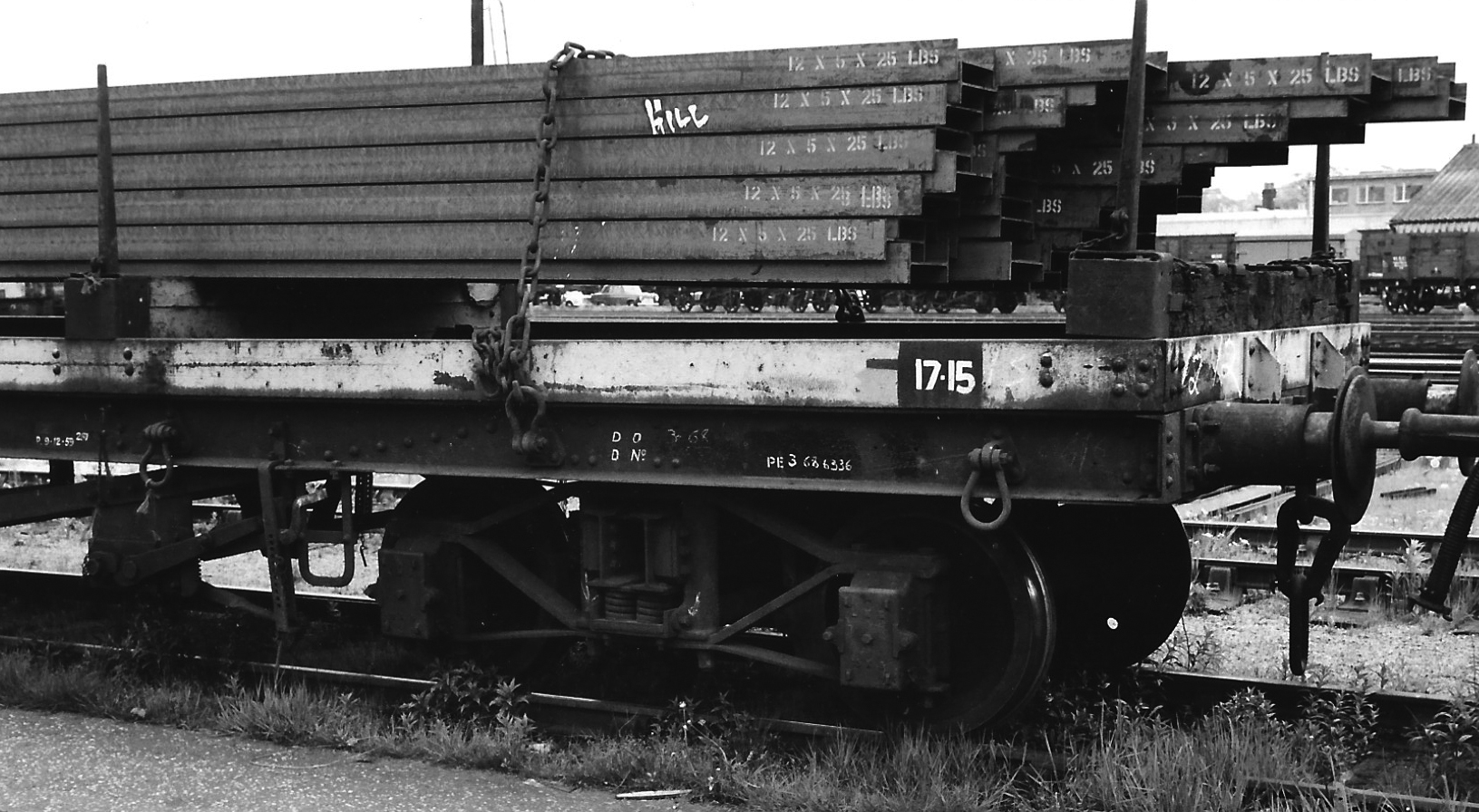
Plate 2/2 As close up of the bogie of No. M720720. One wonders whether the overhanging beams are the
result of a rough shunt! (Author, ref: 35/86-23)
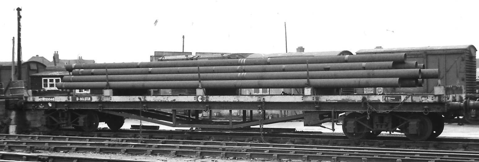
Plate 2/3 The 42-ton version to diagram 18C, No. M720046 was built at Derby in 1948 and is here loaded
with steel tubes from which the binding chains have been released when at Feltham in 1967. (Author,
ref: 35/78-22)
The 52-foot bogie bolster wagons, described above, had been preceded by 62-foot long 50-ton wagons (23). These were probably intended for the transport of 60-foot rails which at that length are easily crippled unless adequately supported. Wagons of such a length require substantial longitudinal members to be able to carry the high load. The main frames were, therefore, made up of six 10-inch by 6-inch rolled steel joists and deliberately fabricated with one-inch pre-camber to counter act elastic deflection under load. To accommodate the longitudinal bracing angles, the inner bottom flanges were planed back at the approach to the position of the bogies. The headstocks were a 12-inch deep channel section, to which 3-link couplings and oval buffers were fitted.
On all wagons 2ft 8½in diameter 3-hole disc wheels with oil lubricated journal axle-boxes 11in by 5½in diameter (24) supported by 2-foot long eight leaf springs mounted in 8-foot wheel base channel and plate frame bogies with angle tie bars between horns. The bogie centres of the first four diagrams were at 48 feet, but this was decreased to 45 feet for the last three diagrams (25). The compound lever hand brake was mounted diagonally opposite on the right-hand side of each bogie. The floor was two-inch thick wooden planks without kerb rails, but included a hinged end plank that could be folded down onto top of the buffers at each end. Sheet cleats were fitted to vehicles to diagrams 19A and 19C.
The height from rail level to the top of the bolsters varies considerably between different diagrams. Those above 5-feet will have been more suitable for carrying long flat loads, such as rails and steel sections, enabling lifting chains or strops to be passed beneath prior to lifting. Whereas the Engineer used these wagons for conveying prefabricated track panels, where the sleeper rested on the wagon floor and were normally raised by engaging a lifting bale around the rail head. In these circumstances, the lower the bolster could be made, the greater the possibility of being able to add an additional panel to the load within the loading gauge, for which the absence of any kerb rails will have assisted.
Those wagons numbered 72xxxx were revenue earning vehicles, whereas those numbered 74xxxx were allocated to the Engineer's Department. All are thought to have been coded 'BBP' by the LMS, some having cast iron plates attached to the solebar towards the left-hand end. BR distinguished between those in revenue earning traffic as 'Borail MB, MC, MD or G', while the code 'Salmon' was allocated to the Engineer's Department.
This design was initially perpetuated by BR into the 50-ton Salmon wagons as diagrams 640 and 646 with plate bogies, steel floor, screw hand brake and a box for binding chains for use by the Engineer's Department throughout the network. They were then developed with through vacuum pipe to diagrams 628 and 637 (26).
| LMS 62-Foot 50-Ton Bogie Bolster Wagons | ||||||||||
|---|---|---|---|---|---|---|---|---|---|---|
| Page in SCV book | Drg Nos | Tare (T‑c) | Lot Nos | Built at | No built | Year built | Nos | Ht. of bolster (ft‑in) | Wagon Codes | |
| LMS | BR | |||||||||
| 19A | 11/188 | 25-5 | 420 | Derby | 12 | 1929 | 168908‑19 | 5-0⅝ | BBP | Borail G |
| 19B | 11/281B | 24-10 | 988 1138 | Fairfield Fairfield | 8 30 | 1936/7 1939 | 720900‑7 720908‑37 | 5-3½ | BBP | Borail MB |
| 19C | 11.294 & 14/2945 | 23-10 | 1080 1146 | Wolverton Wolverton | 2 13 | 1937 1938/9 | 748000‑1 748002‑14 | 4-6½ | u/k | |
| 19D | 11/325 & 14/2945A | 23-5 | 1159 | Wolverton | 25 | 1939 | 748015‑39 | 4-2⅞ | u/k | |
| 19E | 11/427 & 14/2945 | 23-2 | 1286 1292 | Wolverton Wolverton | 25 25 | 1940 1940 | 748040‑64 721025‑49 | 4-2¾ | BBP | Borail MC |
| 19F | 11/438 & 14/2945 | 24-18 | 1293 | Wolverton | 25 | 1941 | 720938‑62 | 5-3⅜ | BBP | Borail MD |
| 19G | 11/452 & 14/2945 | 23-18 | 1319 | Wolverton | 25 | 1942 | 748065‑89 | 4-6⅜ | u/k | Borail EM |
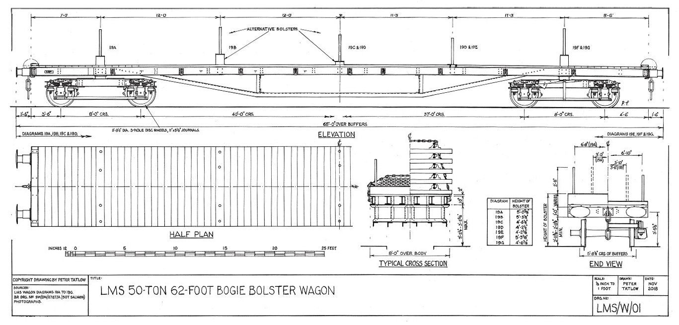
Figure 3.1 Drawing of LMS 50-ton 62-foot bogie bolster wagon. (Author)

Plate 3/1 An official photograph of LMS 50-ton 62-foot bogie bolster wagon No.721000 as built in July
1942. This wagon has bogies at 45-foot centres and the nominal height bolsters suggest to diagram 19E.
It is presumed this wagon was renumbered. It appears as if a chain box has been fitted within the
trussing on the far side. These were a feature of BR Salmon wagons, but do not show in photographs of
any other LMS wagon. (LMS, author's collection, ref: DY27161)
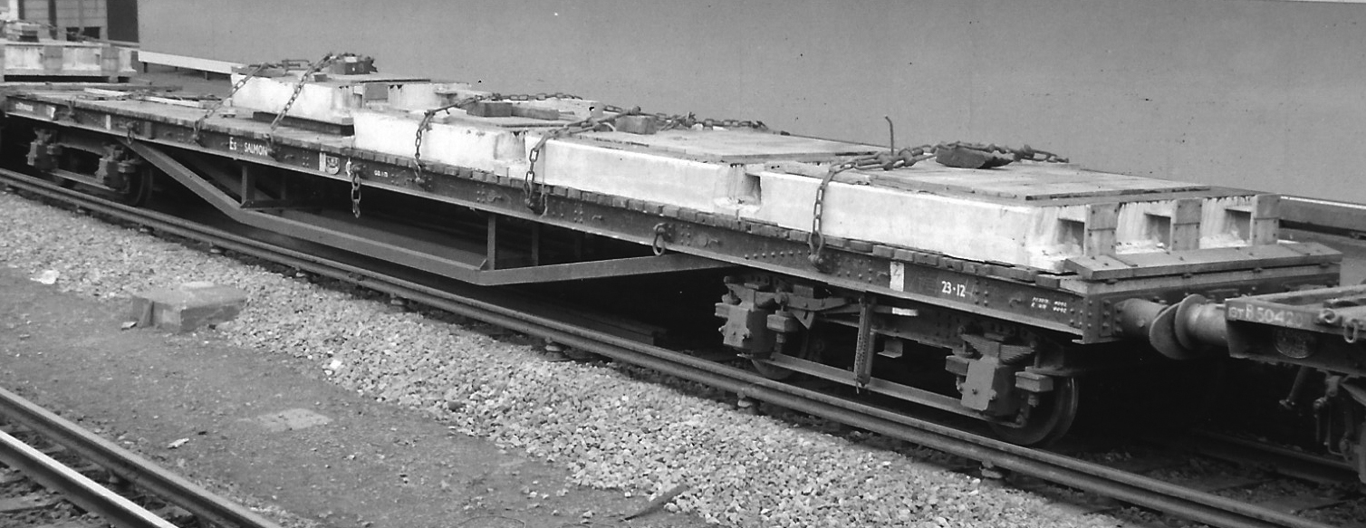
Plate 3/2 An unidentified ex-LMS 50-ton bogie bolster wagon with bogies at 48-foot centres seen here at
Vauxhall loaded with concrete encased steel deck units required in connection with the renewal of Bridge
No. A30 being carried out within the station on 27 March 1971. (Author, ref: 35/103-8)
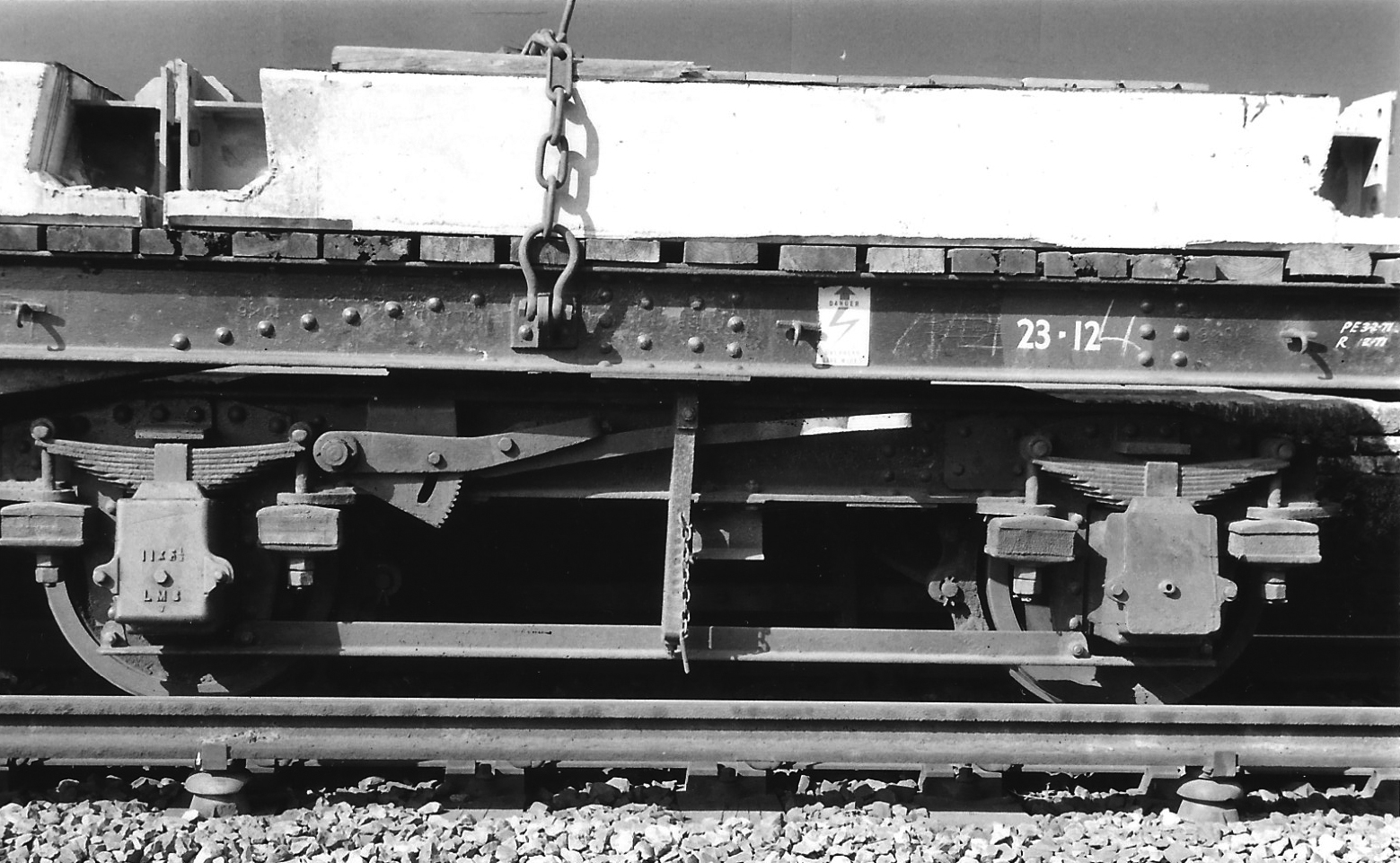
Plate 3/3 A close up of the right-hand bogie showing the short compound brake lever and ratchet.
(Author, ref: 35/102-36A)
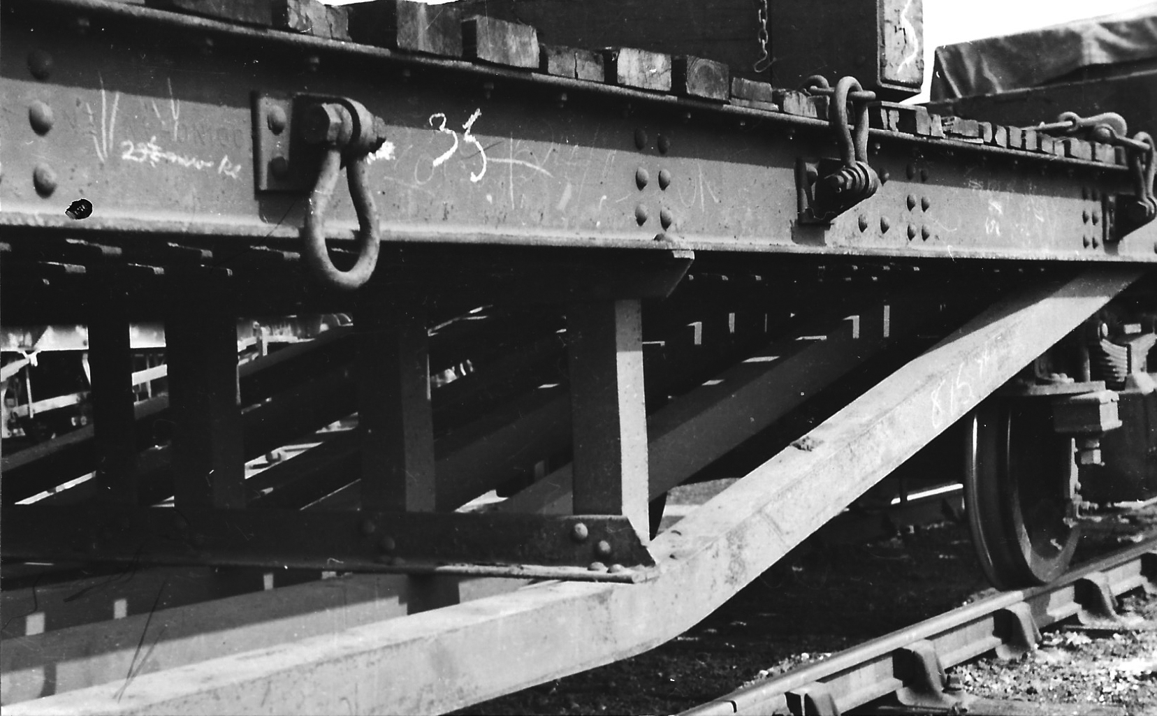
Plate 3/4 The arrangement the trussing and queen post of No. 721039 at Eastleigh on 21 May 1949. (AE
West, courtesy M King, ref: 1667)
Site contents Copyright © LMS Society, 2024
April 20th, 2024
Site contents Copyright © LMS Society, 2024